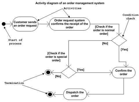
http://www.tutorialspoint.com/uml/uml_activity_diagram.htm and http://www.tutorialspoint.com/images/uml_activity_diagram.jpg show off how UML should look.- A black dot is the start of a process.
- A black dot with a circle around it is an end point for the process.
- A diamond is a decision. A question will be written before the inbound arrow, and the lines that lead out ultimately as other arrows to elsewhere will have a choice written at their heads.
- An oval is a stop along the trip to the destination.
- Arrows are drawn between the four items above.
- Centering copy in a terminator (oval) can keep it from bleeding out the side of the oval.
- For a Basic Flowchart Visio project use the Dynamic Connector to draw lines (with arrows at one end) between two shapes.
- Grab a green node on a oval to drag out its shape and make it fatter or thiner.
- I can't seem to make a Dynamic Connector arrow end midway into a another Dynamic Connector arrow in Visio, however if I just connect to where the arrow ultimately leads to anyway, the desired effect is created for me.
- One may drag about middle segments of Dynamic Connector arrows to the right and left or up and down to reposition them.
- Don't try to center copy in an oval vertically with line breaks. Drag the oval vertically to change its shape.
- If an arrow has too many bends in it, one may remove two segments by dragging two segements that are one segment apart parallel.
- You may open Visio documents in IE!
Tuesday, September 25, 2012
UML in Visio
Subscribe to:
Post Comments (Atom)
No comments:
Post a Comment